§ 01
Overview
This project was the final deliverable for BCIT's Advanced Routing Services course, part of the Computing Information Systems Administration (CISA) program. The goal was to design and implement a production-representative network infrastructure spanning both Service Provider (SP) and Customer Edge (CE) layers using Cisco hardware.
The topology simulates a real-world multi-site enterprise WAN: a central Provider Edge router connects to four Customer Edge routers across geographically separate sites, with all inter-site traffic tunnelled securely through DMVPN.
Key Technologies
- DMVPNDynamic Multipoint VPN — hub-and-spoke tunnels (GRE Multipoint) providing secure site-to-site connectivity through the Provider Edge.
- MPLSMulti-Protocol Label Switching — label-switched forwarding on CE routers for optimised path selection across the provider backbone.
- HSRPHot Standby Router Protocol — virtual gateway redundancy across L3 switches; immediate failover if the active router goes down.
- MSTPMultiple Spanning Tree Protocol — VLAN-aware STP instances for loop prevention and load balancing across the switch block.
- EtherChannelLogical link aggregation on S1, S2, and S3 — provides fault tolerance and additional bandwidth between switching devices.
- NATNetwork Address Translation — configured on both PE and CE routers to allow internal networks internet access.
- OSPFOpen Shortest Path First — routing protocol across all devices for neighbour discovery and route propagation; Area 16.
§ 02
Topology
The network is structured around a central Provider Edge router (R1) that connects to the internet via DHCP and acts as the NAT boundary and OSPF default-information originator for the entire domain. Four Customer Edge routers (R2–R5) connect to R1 through provider-facing VLANs and form a DMVPN spoke network.
Below R4 and R5 sits the switch block: two Layer 3 switches (S1 and S2) running HSRP and MSTP, interconnected with EtherChannel port-channels, feeding a Layer 2 access switch that connects end devices.
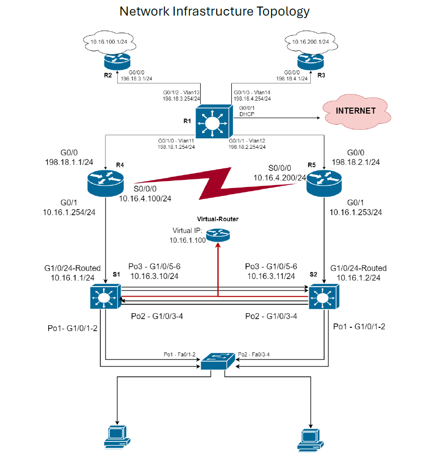 Figure 1 — Network Infrastructure Topology
§ 03
Switch Block
EtherChannel
All three switches use EtherChannel to bundle physical links into single logical port-channels, providing both redundancy and aggregated bandwidth. S1 initiates channels in Desirable / Active mode; S2 responds in Auto / Passive mode for PAgP and LACP compatibility respectively. All port-channel interfaces carry Native VLAN 333 and allow VLANs 10–15, 222, and 333.
| Device | Port-Channel | Interfaces | Mode | Type |
|---|---|---|---|---|
| S1 | Po1 | G1/0/1-2 | Desirable | Layer 2 trunk |
| S1 | Po2 | G1/0/3-4 | Desirable | Layer 2 trunk |
| S1 | Po3 | G1/0/5-6 | Active | Layer 3 routed |
| S2 | Po1 | G1/0/1-2 | Desirable | Layer 2 trunk |
| S2 | Po2 | G1/0/3-4 | Auto | Layer 2 trunk |
| S2 | Po3 | G1/0/5-6 | Passive | Layer 3 routed |
| L2-S1 | Po1 | Fa0/1-2 | Auto | Layer 2 trunk |
| L2-S1 | Po2 | Fa0/3-4 | Auto | Layer 2 trunk |
MSTP & HSRP
Multiple Spanning Tree Protocol is configured with two instances: S1 is the primary root for VLANs 10–11; S2 is the primary root for VLANs 12–14. This distributes STP convergence load and prevents a single root election bottleneck.
HSRP creates a virtual gateway (VIP) for each VLAN. S1 holds active status at priority 110; S2 is standby at priority 90. On S1 failure, S2 immediately assumes the virtual IP and traffic continues without manual intervention.
| VLAN | Name | S1 IP | S2 IP | HSRP VIP |
|---|---|---|---|---|
| V10 | Data | 10.16.10.254 | 10.16.10.253 | 10.16.10.252 |
| V11 | Voice | 10.16.11.254 | 10.16.11.253 | 10.16.11.252 |
| V12 | Server | 10.16.12.254 | 10.16.12.253 | 10.16.12.252 |
| V13 | Wireless | 10.16.13.254 | 10.16.13.253 | 10.16.13.252 |
| V14 | Guest | 10.16.14.254 | 10.16.14.253 | 10.16.14.252 |
| V15 | NetMgmt | 10.16.15.254 | 10.16.15.253 | 10.16.15.252 |
§ 04
Routing & WAN
OSPF
OSPF Area 16 runs across all devices. R1 uses default-information originate
to push the internet default route into the OSPF domain. All CE routers advertise their
site-local networks (10.16.0.0 and 198.18.0.0 summaries) via OSPF,
ensuring full reachability between sites without static routing.
DMVPN
Dynamic Multipoint VPN Phase 2 tunnels are established between all CE routers through
the Provider Edge. R2 acts as the hub router; R3, R4, and R5 are spokes. Tunnel interfaces
use GRE Multipoint mode with G0/0/0 as the tunnel source on each CE router.
This allows spoke-to-spoke traffic to build dynamic tunnels on demand rather than routing
all inter-site traffic through the hub.
| Router | Role | Tunnel IP | Site Network |
|---|---|---|---|
| R2 | Hub | 50.16.1.2 | 10.16.100.0/24 |
| R3 | Spoke | 50.16.1.3 | 10.16.200.0/24 |
| R4 | Spoke | 50.16.1.4 | 10.16.1.0/24 (Site 1) |
| R5 | Spoke | 50.16.1.5 | 10.16.2.0/24 (Site 1) |
MPLS
Multi-Protocol Label Switching is enabled on CE routers (R2–R5) on both their WAN-facing and LAN-facing interfaces. Labels are applied to each packet, allowing the provider backbone to forward traffic along the shortest label-switched path rather than performing full IP lookups at each hop.
§ 05
IP Addressing
| Device | Interface | IPv4 Address | IPv6 Address |
|---|---|---|---|
| R1 (PE) | G0/0/1 | DHCP | — |
| G0/1/0 (V11) | 198.18.1.254/24 | 2001:198:18:1::254/64 | |
| G0/1/1 (V12) | 198.18.2.254/24 | 2001:198:18:2::254/64 | |
| G0/1/2 (V13) | 198.18.3.254/24 | 2001:198:18:3::254/64 | |
| G0/1/3 (V14) | 198.18.4.254/24 | 2001:198:18:4::254/64 | |
| R4 (CE) | G0/0 | 198.18.1.1/24 | 2001:198:18:1::1/64 |
| G0/1 (Site 1) | 10.16.1.254/24 | 2001:10:16:1::254/64 | |
| S0/0/0 | 10.16.4.100/24 | 2001:10:16:4::100/64 | |
| R5 (CE) | G0/0 | 198.18.2.1/24 | — |
| G0/1 (Site 1) | 10.16.2.254/24 | 2001:10:16:2::254/64 | |
| S0/0/0 | 10.16.4.200/24 | 2001:10:16:4::200/64 | |
| R2 (CE) | G0/0/0 | 198.18.3.1/24 | 2001:198:18:3::1/64 |
| G0/0/1 (Site 2) | 10.16.100.1/24 | 2001:172:16:1::1/64 | |
| R3 (CE) | G0/0/0 | 198.18.4.1/24 | 2001:198:18:5::1/64 |
| G0/0/1 (Site 3) | 10.16.200.1/24 | 2001:172:16:2::1/64 | |
| S1 | G1/0/24 Routed | 10.16.1.1/24 | 2001:10:16:1::1/64 |
| S2 | G1/0/24 Routed | 10.16.1.2/24 | 2001:10:16:1::2/64 |
§ 06
Results
All primary objectives were successfully verified through ping tests, traceroutes, and deliberate failure injection.
Layer 2 — Switching
- MSTPVLAN 10 traffic routed through S1 (primary root); VLAN 30 traffic routed through S2 — confirming instance-based load balancing.
- EtherChannelShutdown of G1/0/5 on Po3 (routed link between S1 and S2) — S1 maintained connectivity to S2 through the surviving port, confirming fault tolerance.
Layer 3 — Routing & WAN
- OSPFFull route propagation and neighbour adjacency confirmed across all routers. All sites reached each other, the ISP, and the internet.
- DMVPNSuccessful pings through GRE tunnels from all spokes to the hub and between spokes.
- HSRPS1 powered down — end device on VLAN 10 maintained connectivity to the R2 site via S2 assuming the virtual IP.
- MPLSTraceroute confirmed label-switched forwarding; each CE router selected the shortest label path.
§ 07
Known Limitations & Improvements
- OSPFOSPF neighbour adjacency uses broadcast mode. Switching to multicast would reduce hello traffic overhead and improve convergence speed across the domain.
- HSRPSerial link IP addresses on R4 and R5 were not configured — HSRP tracking against these interfaces is not possible until addressing is applied.